Road cross section drawing pdf
Road cross section drawing pdf
13 Understand the construction of Water Bound Macadam (WBM) road. 6.2 Describe the process of drawing the cross section of RCC retaining wall.
FDOT Subassemblies Essentials Session Objectives: Cross Sections Requirements to Create Cross Sections and Plan Profile .dwgs. Review what objects are required on your drawing …
25/02/2015 · This tutorial helps to you that how to draw existing road cross section using Excel and AutoCAD.
Sections & Drawings 2000 . SECTION Miscellaneous Design Details 2000 NO. DATE TITLE 2013 09-29-92 Typical Half Section of Auxiliary Lane Through Areas of Superelevation 2000 Typical Index pg. 1 04-20-10. SECTION Stage Improvement 2600 NO. DATE TITLE 2602 10-15-13 Typical Cross Section HMA Resurfacing 2603 08-30-88 Typical Cross Section Grading and Shouldering 2607 10-02-01 …
24/05/2017 · earth work calculation software anybody need the software . How to draw road cross section using Excel and AutoCAD Tutorials.This tutorial helps to you that how to draw existing road cross section
Select Cross Section 9+00 [0+280] by clicking on it in the list and notice how the view updates to the selected cross section. The cross sections automatically include all objects in the model. At this location the parking area next to the road is also visible.
Cross Section Elements 5-1 CHAPTER 5 CROSS SECTION ELEMENTS 5.1 PAVEMENT TYPICAL SECTIONS Roadway typical sections are developed for each different roadway type within the project. During the Pre-Design Conference, the actual typical section widths, slopes, and other geometric controls to be used will be determined as guided by the Design Standards. Page 4 of the Pre-Design …
Index of Drawings CONSTRUCTION CROSS-SECTION DRAWINGS AND GUIDE SPECIFICATIONS FOR CAMBRIDGE INTERLOCKING PAVINGSTONES 01 Residential Driveway With Concrete Edges
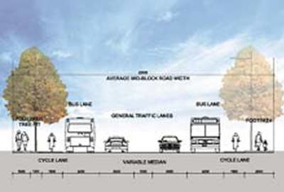
the standards laid out in the Auckland Transport Code of Practice. 7.4.2 Road Reserve Cross Section The road reserve is made up of a number of different elements that form the overall cross section. These elements include the following items: Berms (may include service trenches), footways and carriageways (split in to various lane configurations and might include a flush/solid median). The
The intersections of slope planes in the highway cross section should be well rounded for added safety, increased stability, and improved aesthetics. Front slopes, back slopes, and ditches should be sodded and/or seeded where feasible to promote stability and reduce erosion. In arid regions, concrete or rock retards may be necessary to prevent ditch erosion.
that interact with other drawing objects are seeking out the correct data. With this portion complete, you now have a 3D model of the road design from which you can create surfaces, generate cross-section views, calculate material volumes, and many other design tasks. The Assembly As stated above, the assembly (Figure 2) is one of a trio of objects that comprises the corridor model. It
Road Rehabilitation and Reconstruction Using AUTOCAD Because of this, each cross section of the road often requires an individual design, with special attention to cross slopes, pavement irregularities, and many other potential conditions. Despite these challenges, the designer is required to produce an accurate account of the required material types and quantities. This white paper can
dwn by: apd by: date: dwg no. not to scale date revision road & drainage standards pl
Civil Standard Drawing Register. The Civil Standard Drawing Register is now available for download in two formats, listed by the new numbers and listed by the old numbers.
A cross-section shows the shape of a feature (such as a mountain) viewed from the side, as if cut through with a knife. Cross-sections are constructed using the contour lines on a topographic map. (You may like to refresh your memory
A cross section view is generated by slicing the entire length of the object being sectioned. Click Layout tabCreate View panelSection drop-downFull. Click the view you want to use as the parent view. The start direction arrow appears at the cursor. Click in the drawing area to indicate the start point of the section line. The end direction
WEB – Developer – Standard Drawings.pdf Author: edward.li Created Date: 6/5/2018 8:52:55 AM
Cross section views which’s been cut with horizontal and vertical cross section planes for explain the can’t be seeing parts in views that type and dimensions of inner parts as roof, foundation, slab.
To assist users with updating their collection of Brisbane Standard Drawings, an Amendment Register (Excel – 105kb) is available to download and cross-reference. 0000 series – Preface This category includes the standard drawings index, amendment registers and supplementary notes.
Creating a Geologic Cross-Section SERC

Appendix D Typical Cross Sections Winston Salem
Civil Engineering Standard Drawings The City of Greater Dandenong has over 100 civil engineering standard drawings and printings available for download. Please note that the standard drawings may need to be updated, without prior notice.
typical road cross section of a type 3 access road see kerb detail see edging detail 1500 footway typical road cross section of a type 6 mews 4800 carriageway 1000 footway see kerb detail see edging detail 6000 carriageway 1800 footway see kerb detail see edging detail 1800 footway for highway construction make ups refer to drawing 573/03/024 for footway construction make ups refer to drawing
STANDARD CROSS SECTIONS DEPARTMENT OF TRANSPORT NOTES: 1. For predicted future traffic volumes of 500 – 1000 vpd the standard will depend on traffic mix (numbers of road trains/caravans/buses) and
STANDARD DRAWINGS – ROADING . Page 56 of 309 Rotorua Civil Engineering Industry Standard 2000 (Version 2004) RD 01 – Characteristics of Roads & Streets . Page 57 of 309 Rotorua Civil Engineering Industry Standard 2000 (Version 2004) RD 02 – Standard Berm Details Location of Services . Page 58 of 309 Rotorua Civil Engineering Industry Standard 2000 (Version 2004) RD 03 – Standard Road Cross
How to Calculate Cut and Fill by the Cross-Section Method. Now the cross-section method is not my most favorite method for calculate cut and fill volumes but some of my colleagues like it and it is one of the widely accepted ways to calculate cut and fill so I’m going to go ahead and teach it here anyway.
make a cross-section. Read the instructions to complete the Wolf Creek Crater cross-section below. It has been started… Read the instructions to complete the Wolf Creek Crater cross-section …

Advanced Road Design provides comprehensive support for you to apply String controls wherever they need to, and to assign String controls to any part of a design cross section. Strings are the building blocks in Advanced Road Design, and any alignment can be quickly converted
BOROUGH OF NAUGATUCK STANDARD DETAIL DRAWINGS TABLE OF CONTENTS AUTO AND PEDESTRIAN SURFACES SD-1 Road Cross Section SD-2 Permanent Pavement Repair in …
Schedule 6 – Planning Scheme Policies (Infrastructure Design – Chapter 3 Road Corridor Design) Page 3 Drawing number Drawing title UMS 263 Bus bay slab (standard crossfall)
Standard drawings for roadworks. The standard drawings for roadworks supplement the Austroads Guides and provide additional information on standards and practices for roadworks. The standard drawings are divided into eight sections according to the following types. Standard drawings for roadworks – table of contents [PDF 347 Kb] Pits & subsurface drainage Show more. Standard Drawing …
Typical Cross Section of Highways Roadways. By: Haseeb Jamal / On: Mar 23, 2017 / Notes, Design of, Roads The typical cross section provided by AASHTO for a two lane highway is given below. Also see Road Structure . Highway Cross Section Elements. 1. LANE WIDTH OR HIGHWAY TRAVEL WAY: In meeting oncoming vehicle or passing slower ones, the portion selected by a driver depends …
revisions date drawing standard s1007 typical road cross sections sheet 3 a a original issue feb 09 b b pavement under kerb added oct 11 c c 0.7m distance amendments 26/11/14
1.02 The design of the site services shall be in conformance with the Municipality’s Design Guidelines and Standard Drawings and all Municipal by-laws, and in …

SECTION 18 STANDARD DRAWINGS Roading R01 Standard Urban Road Cross Section 18-29 R02 Kerb and Channel Details 18-30 R03 Standard Plate Crossing Details 18-31
Road Construction Standards – Cross Section Tolerances [PDF 2782 KB] RW-4040 Floodway – General Arrangement – Low Volume Rural Roads – Sheet 1 Of 2 [PDF 5134 KB]
ii September 2004 Chapter 7: Cross Section Road Planning and Design Manual 7 Table of Contents Acknowledgement 7-1 7.1 Introduction 7-1 7.1.1 General 7-1
Drawing Number Description Amendment Date; SR.01 (PDF, 359.8 KB) Index. F February 2014 SR.02 (PDF, 202.2 KB) Typical Cross Sections – Residential Streets
Download our new app to report issues, make payments and find information on the go
Standard Drawing 4083 – Cattle Underpass Cross Section and Guard Fence Treatment [PDF 101 Kb] Standard Drawing 4084 – Guard Fence Transition – Bridge Approaches – Guard Fence to Existing Endpost [PDF 137 Kb]
37919 08 Ch08 308. Cengage
The cross-section looks like figure 11 when it is viewed from straight ahead. Drawing Tools To prepare a drawing, one can use manual drafting instruments (figure 12) or …
SAN FRANCISCO TO SAN JOSE SECTION CALIFORNIA HIGH-SPEED TRAIN PROJECT EIR/EIS APPENDIX C –TYPICAL CROSS SECTIONS U.S. Department of Transportation Page C-1
Drawing a cross-section A cross-section is a slice through a particular feature. 1 Decide where you want the cross-section line to be. To draw the shape of a river valley, the line is best drawn to connect the highest point on either side of the valley, at right-angles to the river. 2 Put the straight edge of a piece of scrap paper along your cross-section line. Mark the beginning and end of
o Estate name Stage XXX – Combined road and drainage drawings (coloured single document) o Estate name Stage XXX – Water main reticulation plans (single document)
various cross-sectional elements are important aspects to be considered in this regard. They are explained brie y in this chapter. 12.2 Pavement surface characteristics For safe and comfortable driving four aspects of the pavement surface are important; the friction between the wheels and the pavement surface, smoothness of the road surface, the light re ection characteristics of the top of
typical road cross section for 3.5m wide roads typical road cross section for 5.0m wide roads scale 1:100 scale 1:100 eng. consult. no.date revision head office 1204 park street tel: (012) 426 6000 pretoria 0001 south africa ditsela place po box 415 hatfield pretoria 0083 drawing type bridge/structure no. consultant drawing no. sheet drawing location data project number date: route section
Geologic cross sections provided two-dimensional slice of Earth’s subsurface and is used to help understand geologic conditions that occur in specific areas of the cross section. Creating and evaluating cross-section is a very important aspect of the geoscience profession. The following exercise – road to emmaus sermon pdf Road hierarchy plans and cross-sections The adopted road hierarchy for Mackay is based on the Eppell Olsen & Partners Four Level Road Hierarchy based on the purpose, function, management and design elements of each road in the network.
Download this free CAD drawing of a road cross section. This CAD model can be used in your highway design CAD drawings. (AutoCAD 2004 format) Our free CAD block library is regularly updated.
SECTION 6: CROSS SECTION March 2002 6 – 1 Provisional Issue Draft: S6-Cross Secti on_7-3-02 Draft.wpd – 8 March 2002 (10:24AM) 6 Cross Section 6.1 Introduction 6.1.1 General The cross section of a road is a vertical plane at right angles to the road control line. It is viewed in the direction of increasing stationing and shows transverse detail of the various elements that make up the road’s
2 a 2 b 2 c typical highway cross sections wide paved shoulders posted speed = 35 mph or less 50’ min. right of way 10′ 10′ 4′ p.s. 4′ p.s. 6′ 6′ wide paved shoulders
The Department has adopted the following set of VicRoads Standard drawings, to be read in conjunction with State Growth Specification Sec: 730 – Traffic Signal Installation (based on the VicRoads Standard Section).
Annotation of road cross-section profile description and transitions in profile on long-section based on cross-section information Output in high quality final drawing format in AutoCAD. This allows for further editing and enhancement if required prior to plotting
Title: Typical Cross Sections Residential Streets Author: Gold Coast City Council Subject: Planning Scheme Policy 11 – Land Development Guidelines
Geometric design of roads Jump to and cross-section. Combined, they provide a three-dimensional layout for a roadway. The alignment is the route of the road, defined as a series of horizontal tangents and curves. The profile is the vertical aspect of the road, including crest and sag curves, and the straight grade lines connecting them. The cross section shows the position and number of
ROAD DESIGN Standards & Guidelines K DP 015 – Cross Section DOCUMENT AMENDMENT RECORD Purpose The ‘Cross Section’ drawing is used to show the vertical relationship between the designed and existing surfaces. For examples of this standard see attached drawings. The details listed below can be arranged on the General Construction drawing provided they do not cause the drawing …
Added Cross Section Drawing for BGA (STACKED DIE) Package [Page 9] 2. Updated WLCSP Cross Section Drawing [Page 13] 3. Change Document Title from Package Cross – Section to PACKAGE CROSS – SECTION DRAWINGS [Page 1] 4. Add Month and Year on the first page to reflect the date of revision / update [Page 1] Rev. 1 JARG ** LMAG Initial Release Revision Owner Description of …
Cross Section View “A”- “A” Scale 1″= 10′ SAMPLE DRAWING SAMPLE DRAWING Boat Ramps Dolphins or Moorings. 53′ 107′ 43′ 4′ 39′ Applicant’s Brick House Deck Property Line To Route 200 V.S.H. 888 to End Lot 6 Miles D. Fixer 401 Doyle Lane Louisville, Virginia 29306 48′ 10′ 70′ Property Line Extended Edge of Channel PAINTER CREEK Existing pier MHW MLW Lot 4 Ben Oaks Route 1 Box …
ers creating cross-sections that document the design. Cross-sections document the road- Cross-sections document the road- way assembly and the existing ground to the alignment’s right and left.
3.3.7 Typical cross section 3-9 3.3.8 Auxiliary lanes 3-10 3.3.9 Intersections 3-10 3.3.10 Road safety 3-13 3.4 Glossary 3-13 3.5 Standard Drawings 3-18 Chapter 3 Road Design Edition 1 Issue 0 . Design Standards for Urban Infrastructure 3.1 General This Chapter sets out the requirements for the design of subdivision roads, arterial roads and rural roads in the ACT. Unless otherwise
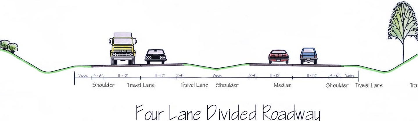
D-1 Appendix D Typical Cross Sections Cross section requirements for roadways vary according to the capacity and level of service to be provided.
9/09/2012 · This is a software that can make hundreds of x-sections in five minutes. please b informed that this is not free.
The cross-section of footpaths and nature strips shall conform to those shown on Standard Drawings. In high activity areas, such as schools and shops, the street verge is usually fully paved
Regional Office – Engineering Road Construction Related Autocad Drawings and Specifications Select an underlined filename to download. CAD Drawings These drawings are created in AutoCad Ver 13 and Ver 14. They are public property and are not for sale. They are made available for professional use by engineers qualified to adapt these drawings to local conditions. The user accepts full liability
S100
TYPICAL CROSS SECTION rms.nsw.gov.au
To Create a Cross Section View AutoCAD Autodesk
Civil Engineering Standard Drawings City of Greater
Road Rehabilitation and Reconstruction Using AutoCAD Civil 3D
Road hierarchy plans and cross-sections mackay.qld.gov.au

Road Construction Related Autocad Drawings and
Chapter 3 Road corridor design Brisbane City Council
– Cross Section Department of Transport and Main Roads
Typical Cross Section of Highways Roadways AboutCivil.Org
CROSS SECTION ELEMENTS Louisiana
RoadMate Road Design Software TechnocadTechnocad
6 Cross Section NZ Transport Agency
Cross sectional elements nptel.ac.in
FDOT Subassemblies Essentials Session Objectives: Cross Sections Requirements to Create Cross Sections and Plan Profile .dwgs. Review what objects are required on your drawing …
Download our new app to report issues, make payments and find information on the go
Cross Section Elements 5-1 CHAPTER 5 CROSS SECTION ELEMENTS 5.1 PAVEMENT TYPICAL SECTIONS Roadway typical sections are developed for each different roadway type within the project. During the Pre-Design Conference, the actual typical section widths, slopes, and other geometric controls to be used will be determined as guided by the Design Standards. Page 4 of the Pre-Design …
Sections & Drawings 2000 . SECTION Miscellaneous Design Details 2000 NO. DATE TITLE 2013 09-29-92 Typical Half Section of Auxiliary Lane Through Areas of Superelevation 2000 Typical Index pg. 1 04-20-10. SECTION Stage Improvement 2600 NO. DATE TITLE 2602 10-15-13 Typical Cross Section HMA Resurfacing 2603 08-30-88 Typical Cross Section Grading and Shouldering 2607 10-02-01 …
typical road cross section for 3.5m wide roads typical road cross section for 5.0m wide roads scale 1:100 scale 1:100 eng. consult. no.date revision head office 1204 park street tel: (012) 426 6000 pretoria 0001 south africa ditsela place po box 415 hatfield pretoria 0083 drawing type bridge/structure no. consultant drawing no. sheet drawing location data project number date: route section
the standards laid out in the Auckland Transport Code of Practice. 7.4.2 Road Reserve Cross Section The road reserve is made up of a number of different elements that form the overall cross section. These elements include the following items: Berms (may include service trenches), footways and carriageways (split in to various lane configurations and might include a flush/solid median). The
Advanced Road Design provides comprehensive support for you to apply String controls wherever they need to, and to assign String controls to any part of a design cross section. Strings are the building blocks in Advanced Road Design, and any alignment can be quickly converted
revisions date drawing standard s1007 typical road cross sections sheet 3 a a original issue feb 09 b b pavement under kerb added oct 11 c c 0.7m distance amendments 26/11/14
ROAD DESIGN Standards & Guidelines K DP 015 – Cross Section DOCUMENT AMENDMENT RECORD Purpose The ‘Cross Section’ drawing is used to show the vertical relationship between the designed and existing surfaces. For examples of this standard see attached drawings. The details listed below can be arranged on the General Construction drawing provided they do not cause the drawing …
SECTION 18 STANDARD DRAWINGS Roading R01 Standard Urban Road Cross Section 18-29 R02 Kerb and Channel Details 18-30 R03 Standard Plate Crossing Details 18-31
The cross-section of footpaths and nature strips shall conform to those shown on Standard Drawings. In high activity areas, such as schools and shops, the street verge is usually fully paved
2 a 2 b 2 c typical highway cross sections wide paved shoulders posted speed = 35 mph or less 50’ min. right of way 10′ 10′ 4′ p.s. 4′ p.s. 6′ 6′ wide paved shoulders
Standard drawings for roadworks. The standard drawings for roadworks supplement the Austroads Guides and provide additional information on standards and practices for roadworks. The standard drawings are divided into eight sections according to the following types. Standard drawings for roadworks – table of contents [PDF 347 Kb] Pits & subsurface drainage Show more. Standard Drawing …
PROJECT Contour and cross-section skills
Presentation Drawings Main Roads Western Australia
Drawing a cross-section A cross-section is a slice through a particular feature. 1 Decide where you want the cross-section line to be. To draw the shape of a river valley, the line is best drawn to connect the highest point on either side of the valley, at right-angles to the river. 2 Put the straight edge of a piece of scrap paper along your cross-section line. Mark the beginning and end of
SECTION 18 STANDARD DRAWINGS Roading R01 Standard Urban Road Cross Section 18-29 R02 Kerb and Channel Details 18-30 R03 Standard Plate Crossing Details 18-31
Title: Typical Cross Sections Residential Streets Author: Gold Coast City Council Subject: Planning Scheme Policy 11 – Land Development Guidelines
typical road cross section of a type 3 access road see kerb detail see edging detail 1500 footway typical road cross section of a type 6 mews 4800 carriageway 1000 footway see kerb detail see edging detail 6000 carriageway 1800 footway see kerb detail see edging detail 1800 footway for highway construction make ups refer to drawing 573/03/024 for footway construction make ups refer to drawing
Sections & Drawings 2000 . SECTION Miscellaneous Design Details 2000 NO. DATE TITLE 2013 09-29-92 Typical Half Section of Auxiliary Lane Through Areas of Superelevation 2000 Typical Index pg. 1 04-20-10. SECTION Stage Improvement 2600 NO. DATE TITLE 2602 10-15-13 Typical Cross Section HMA Resurfacing 2603 08-30-88 Typical Cross Section Grading and Shouldering 2607 10-02-01 …
Select Cross Section 9 00 [0 280] by clicking on it in the list and notice how the view updates to the selected cross section. The cross sections automatically include all objects in the model. At this location the parking area next to the road is also visible.
SAN FRANCISCO TO SAN JOSE SECTION CALIFORNIA HIGH-SPEED TRAIN PROJECT EIR/EIS APPENDIX C –TYPICAL CROSS SECTIONS U.S. Department of Transportation Page C-1
FDOT Subassemblies Essentials Session Objectives: Cross Sections Requirements to Create Cross Sections and Plan Profile .dwgs. Review what objects are required on your drawing …
2 a 2 b 2 c typical highway cross sections wide paved shoulders posted speed = 35 mph or less 50’ min. right of way 10′ 10′ 4′ p.s. 4′ p.s. 6′ 6′ wide paved shoulders
SECTION 6: CROSS SECTION March 2002 6 – 1 Provisional Issue Draft: S6-Cross Secti on_7-3-02 Draft.wpd – 8 March 2002 (10:24AM) 6 Cross Section 6.1 Introduction 6.1.1 General The cross section of a road is a vertical plane at right angles to the road control line. It is viewed in the direction of increasing stationing and shows transverse detail of the various elements that make up the road’s
The cross-section of footpaths and nature strips shall conform to those shown on Standard Drawings. In high activity areas, such as schools and shops, the street verge is usually fully paved
A cross section view is generated by slicing the entire length of the object being sectioned. Click Layout tabCreate View panelSection drop-downFull. Click the view you want to use as the parent view. The start direction arrow appears at the cursor. Click in the drawing area to indicate the start point of the section line. The end direction
STANDARD CROSS SECTIONS DEPARTMENT OF TRANSPORT NOTES: 1. For predicted future traffic volumes of 500 – 1000 vpd the standard will depend on traffic mix (numbers of road trains/caravans/buses) and
Cross sectional elements nptel.ac.in
Hume City Council Road & Drainage Standard Drawings
Road Rehabilitation and Reconstruction Using AUTOCAD Because of this, each cross section of the road often requires an individual design, with special attention to cross slopes, pavement irregularities, and many other potential conditions. Despite these challenges, the designer is required to produce an accurate account of the required material types and quantities. This white paper can
SECTION 18 STANDARD DRAWINGS Roading R01 Standard Urban Road Cross Section 18-29 R02 Kerb and Channel Details 18-30 R03 Standard Plate Crossing Details 18-31
Cross section views which’s been cut with horizontal and vertical cross section planes for explain the can’t be seeing parts in views that type and dimensions of inner parts as roof, foundation, slab.
typical road cross section of a type 3 access road see kerb detail see edging detail 1500 footway typical road cross section of a type 6 mews 4800 carriageway 1000 footway see kerb detail see edging detail 6000 carriageway 1800 footway see kerb detail see edging detail 1800 footway for highway construction make ups refer to drawing 573/03/024 for footway construction make ups refer to drawing
revisions date drawing standard s1007 typical road cross sections sheet 3 a a original issue feb 09 b b pavement under kerb added oct 11 c c 0.7m distance amendments 26/11/14
To assist users with updating their collection of Brisbane Standard Drawings, an Amendment Register (Excel – 105kb) is available to download and cross-reference. 0000 series – Preface This category includes the standard drawings index, amendment registers and supplementary notes.
D-1 Appendix D Typical Cross Sections Cross section requirements for roadways vary according to the capacity and level of service to be provided.
Select Cross Section 9 00 [0 280] by clicking on it in the list and notice how the view updates to the selected cross section. The cross sections automatically include all objects in the model. At this location the parking area next to the road is also visible.
Design Guidelines and Standard Drawings Home – Clarington
To Create a Cross Section View AutoCAD Autodesk
To assist users with updating their collection of Brisbane Standard Drawings, an Amendment Register (Excel – 105kb) is available to download and cross-reference. 0000 series – Preface This category includes the standard drawings index, amendment registers and supplementary notes.
D-1 Appendix D Typical Cross Sections Cross section requirements for roadways vary according to the capacity and level of service to be provided.
o Estate name Stage XXX – Combined road and drainage drawings (coloured single document) o Estate name Stage XXX – Water main reticulation plans (single document)
24/05/2017 · earth work calculation software anybody need the software . How to draw road cross section using Excel and AutoCAD Tutorials.This tutorial helps to you that how to draw existing road cross section
that interact with other drawing objects are seeking out the correct data. With this portion complete, you now have a 3D model of the road design from which you can create surfaces, generate cross-section views, calculate material volumes, and many other design tasks. The Assembly As stated above, the assembly (Figure 2) is one of a trio of objects that comprises the corridor model. It
Regional Office – Engineering Road Construction Related Autocad Drawings and Specifications Select an underlined filename to download. CAD Drawings These drawings are created in AutoCad Ver 13 and Ver 14. They are public property and are not for sale. They are made available for professional use by engineers qualified to adapt these drawings to local conditions. The user accepts full liability
typical road cross section of a type 3 access road see kerb detail see edging detail 1500 footway typical road cross section of a type 6 mews 4800 carriageway 1000 footway see kerb detail see edging detail 6000 carriageway 1800 footway see kerb detail see edging detail 1800 footway for highway construction make ups refer to drawing 573/03/024 for footway construction make ups refer to drawing
ers creating cross-sections that document the design. Cross-sections document the road- Cross-sections document the road- way assembly and the existing ground to the alignment’s right and left.
Schedule 6 – Planning Scheme Policies (Infrastructure Design – Chapter 3 Road Corridor Design) Page 3 Drawing number Drawing title UMS 263 Bus bay slab (standard crossfall)
STANDARD CROSS SECTIONS DEPARTMENT OF TRANSPORT NOTES: 1. For predicted future traffic volumes of 500 – 1000 vpd the standard will depend on traffic mix (numbers of road trains/caravans/buses) and
The Department has adopted the following set of VicRoads Standard drawings, to be read in conjunction with State Growth Specification Sec: 730 – Traffic Signal Installation (based on the VicRoads Standard Section).
Cross section views which’s been cut with horizontal and vertical cross section planes for explain the can’t be seeing parts in views that type and dimensions of inner parts as roof, foundation, slab.
make a cross-section. Read the instructions to complete the Wolf Creek Crater cross-section below. It has been started… Read the instructions to complete the Wolf Creek Crater cross-section …
PROJECT Contour and cross-section skills
Road Construction Related Autocad Drawings and
Cross Section Elements 5-1 CHAPTER 5 CROSS SECTION ELEMENTS 5.1 PAVEMENT TYPICAL SECTIONS Roadway typical sections are developed for each different roadway type within the project. During the Pre-Design Conference, the actual typical section widths, slopes, and other geometric controls to be used will be determined as guided by the Design Standards. Page 4 of the Pre-Design …
Cross Section View “A”- “A” Scale 1″= 10′ SAMPLE DRAWING SAMPLE DRAWING Boat Ramps Dolphins or Moorings. 53′ 107′ 43′ 4′ 39′ Applicant’s Brick House Deck Property Line To Route 200 V.S.H. 888 to End Lot 6 Miles D. Fixer 401 Doyle Lane Louisville, Virginia 29306 48′ 10′ 70′ Property Line Extended Edge of Channel PAINTER CREEK Existing pier MHW MLW Lot 4 Ben Oaks Route 1 Box …
A cross section view is generated by slicing the entire length of the object being sectioned. Click Layout tabCreate View panelSection drop-downFull. Click the view you want to use as the parent view. The start direction arrow appears at the cursor. Click in the drawing area to indicate the start point of the section line. The end direction
Select Cross Section 9 00 [0 280] by clicking on it in the list and notice how the view updates to the selected cross section. The cross sections automatically include all objects in the model. At this location the parking area next to the road is also visible.
Annotation of road cross-section profile description and transitions in profile on long-section based on cross-section information Output in high quality final drawing format in AutoCAD. This allows for further editing and enhancement if required prior to plotting
Drawing a cross-section A cross-section is a slice through a particular feature. 1 Decide where you want the cross-section line to be. To draw the shape of a river valley, the line is best drawn to connect the highest point on either side of the valley, at right-angles to the river. 2 Put the straight edge of a piece of scrap paper along your cross-section line. Mark the beginning and end of
Title: Typical Cross Sections Residential Streets Author: Gold Coast City Council Subject: Planning Scheme Policy 11 – Land Development Guidelines
ROAD DESIGN Standards & Guidelines K DP 015 – Cross Section DOCUMENT AMENDMENT RECORD Purpose The ‘Cross Section’ drawing is used to show the vertical relationship between the designed and existing surfaces. For examples of this standard see attached drawings. The details listed below can be arranged on the General Construction drawing provided they do not cause the drawing …
the standards laid out in the Auckland Transport Code of Practice. 7.4.2 Road Reserve Cross Section The road reserve is made up of a number of different elements that form the overall cross section. These elements include the following items: Berms (may include service trenches), footways and carriageways (split in to various lane configurations and might include a flush/solid median). The

Geologic cross sections provided two-dimensional slice of Earth’s subsurface and is used to help understand geologic conditions that occur in specific areas of the cross section. Creating and evaluating cross-section is a very important aspect of the geoscience profession. The following exercise
Appendix C Typical Cross Sections text
TYPICAL ROAD CROSS SECTION FOR 3.5m WIDE ROADS GIBB
SECTION 18 STANDARD DRAWINGS Roading R01 Standard Urban
ROAD DESIGN Standards & Guidelines K DP 015 – Cross Section DOCUMENT AMENDMENT RECORD Purpose The ‘Cross Section’ drawing is used to show the vertical relationship between the designed and existing surfaces. For examples of this standard see attached drawings. The details listed below can be arranged on the General Construction drawing provided they do not cause the drawing …
Typical Cross Section of Highways Roadways AboutCivil.Org